CONVERTING FS2004 AIRCRAFT TO FSX TUTORIAL
TABLE OF CONTENTS
Introduction and Downloads
Part 1: Setup
Part 2: Saving and Animating the Props
Part 3: FS2004 Import
Part 4: Setting Up Landing and Taxi Lights
Part 5: Conversion to FSX
Part 6: Editing Materials and Textures
Part 7: VC & Appendix
PART TWO - SAVING THE OTHER PROP PARTS AND ANIMATING THEM
NOTE:
I have found that this process can easily lead to displaced parts, so
be sure to do these steps in the following order, including Exporting
the model after each step. If you still get displaced parts,
refer to Part 5, Step 16.
IMPORT FS2004 AIRCRAFT AND DISPLAY SLOW PROPS
0.
First we need to check that this plane does not have a
rotation= line in the aircraft.cfg file, which will cause the props to
not rotate properly in FSX and later. Open the plane's
aircraft.cfg file by double clicking it (if asked, choose Notepad or
Wordpad). Look for the propeller section, and see if there is a
line that starts with rotation=, like this entry for a twin engine
aircraft:
[propeller]
rotation= -1,-1
If this line has
any -1 values, the props will not rotate properly. Just delete
the entire line, it's not needed. If the props end up rotating in
the wrong direction, just reverse the animation of those prop parts
(See Part 5, Step 22).
1. Props in FS consist of three separate parts - prop_still, prop_slow, and prop_blurred.
Most jet fan disks use the same system, but are called
N1_still/slow/blurred. There are several different ways people
deal with this; in my planes the prop_still parts are detailed
propellers used for stopped and very slow rotation, the prop_blurred
parts are solid round disks, and the prop_slow parts are wedges cut out
of the blurred prop disk (the number of wedges is the number of prop
blades). We will import our plane with the engine0/1/2/3
variables set to 0 so the plane displays the prop_still parts. So we need to isolate
the prop_slow and prop_blurred parts from our model, export them
as FSX files, and later merge them into our plane before we convert it to FSX. We do this one prop type at a time.
2. Click Import, set the drop down box to type FS MDL,
and browse to your aircraft's MDL file, in the plane's Model
folder. Click it and click Open. Do not open the copy.
In our example I will Import the dc6b.mdl file found in the
FS/SimObjects/Airplanes/DC-6B CB-16/model folder.
3.
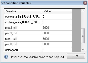
When the Set
Condition Variables box pops up, set the prop0/1/2/3_still variables to
5000. If it does not, this is probably not an FS2004 format aircraft. Upon import this will display the slow props.
You can leave the rest of the numbers unchanged.
FINDING THE SLOW PROPS
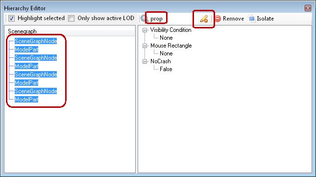
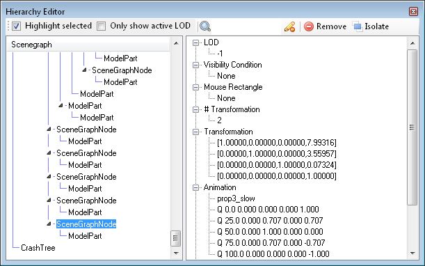
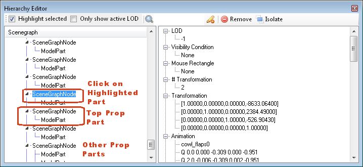
The Hierarchy Editor Explained
4. We will start by exploring the Hierarchy Editor. Note that these images are just examples, and do NOT directly relate to the DC-6B example slow props - that will come in later steps. Click the Hierarchy Editor
button and click the Highlight Selected checkbox. You will see a
tree diagram of your plane's parts on the left. Each time you
click a line in the tree diagram, that part (or group of parts) will
turn red on the aircraft display and the properties of that line will
appear on the right. NOTE:
The pictures below show a plane with stationary props
(propx_still = 0). Yours will look different since you set them
at 5000 (slow props). Refer to #7 below for your prop's
appearance, but learn how to use the Hierarchy Editor here.
The tree diagram appears something like this:
SceneGraphNode
--- this is the master master node - everything is connected to this
node. It is sometimes referred to as the Tick18 or Ambient node.
SceneGraphNode --- This is the master node for this
animated group of parts. The animation is sometimes defined here.
SceneGraphNode --- This node includes another SceneGraphNode (not all
do) - The animation is defined here if not in the first SceneGraphNode.
ModelPart --- These are the parts
themselves (there can be one to many ModelParts within this node).
ModelPart --- There can also be further
SceneGraphNodes and ModelParts as branches of the second
SceneGraphNode, for complex animations.
SceneGraphNode --- This is the master node for this (typically) non-animated group of parts.
ModelPart --- These are the ModelParts
for this node. Again, can be one to many ModelParts.
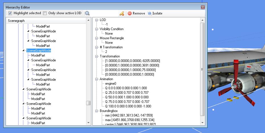
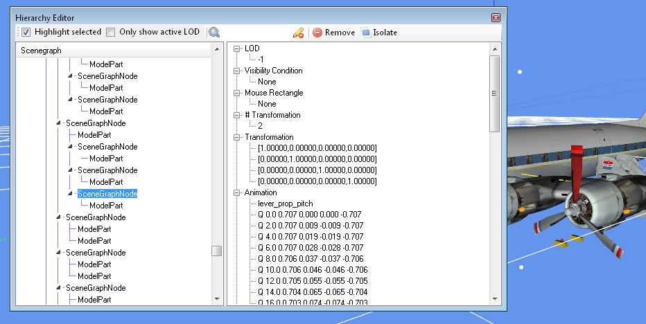
Let's
explore how the Hierarchy Editor works. In the DC-6B example
image above, I have clicked on the prop group of parts for engine #1 (called
engine0 in FS code). You can see that in this case the master
SceneGraphNode for the part contains the animation, assigned to
engine0. This is not a valid FS animation definition, and we will need to change
it later to prop0_still. The prop is a complex part with the hub
the first ModelPart below the master SceneGraphNode (note the red ring
behind the spinner):
and
the three SceneGraphNode/Model part groups below this are each prop
blade. These use the lever_prop_pitch animation definition so
they twist as the prop pitch is adjusted.
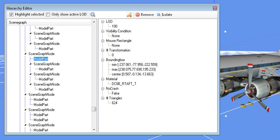
There are two types of properties we will be changing in the Hierarchy Editor, animations and visibility conditions.
Both are displayed in the Property box at the right, if present.
Animations are often assigned to the SceneGraphNodes (but can also be
assigned to ModelParts), while Visibility Conditions must be assigned
to the individual ModelParts.
A ModelPart inherits the animation
from the SceneGraphNodes above it. Thus if the SceneGraphNode has
an animation for the propeller (prop0_still), all the ModelParts
underneath that node will also be so animated. If a
SceneGraphNode or ModelPart under that SceneGraphNode has an animation
of its own, that animation will be added to the original animation.
The example above is the twisting prop blade (lever_prop_pitch)
attached to the prop hub (prop0_still). The prop both rotates and
twists. The same concept applies to visibility conditions.
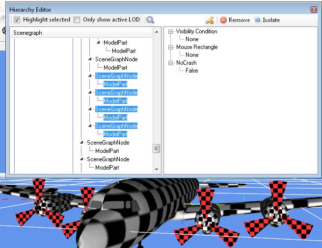
5. To miake identifying parts easier, turn off the textures by clicking the Colored Render Mode button in the bottom row.
6. Open the Hierarchy Editor and type in prop into the search box at the top middle. The slow prop parts will
be listed. Check the Highlight Selected box if not checked.
Click on them and confirm all slow props are there (it will turn red).
Prop0 is the leftmost prop, when you are sitting in the cockpit looking
forward. Now select all of them, using a left click on the top part and a Shift click on the bottom part.
7. With all the parts selected in the list above, click the pencil to the right of the search box (Clear Search)
and the entire list will re-appear. Your parts will still be
selected. As we discussed earlier, a node consists of one or more
SceneGraphNodes and one or more ModelParts. Normally, all these
parts will be together. If not, we will deal with that below.
Ignore the black and white checkerboard in the images below.
ISOLATING THE SLOW PROPS
8.
While there are several different ways of isolating props, most
depend on a specific arrangement of SceneGraphNodes and ModelParts in
the nodes. I'll describe a single procedure that should work for
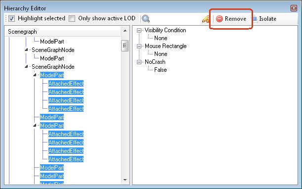
most planes - we will Remove everything that is not the prop parts.
Let's go back to the image of our prop parts (the image
above). Note
that the DC-6B example above only has one ModelPart, but in the image
below I wanted to make it clear to you below that a SceneGraphNode may
contain more than one ModelPart and all of those are to be considered
as part of the prop part. The first job is to remove everything
BELOW the node that
is
highlighted. Do not remove any portion of the last
prop node, including any SceneGraphNodes or ModelParts, just the nodes
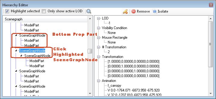
below them. Start by clicking the SceneGraphNode below the bottom
prop part:
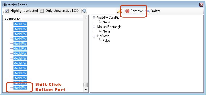
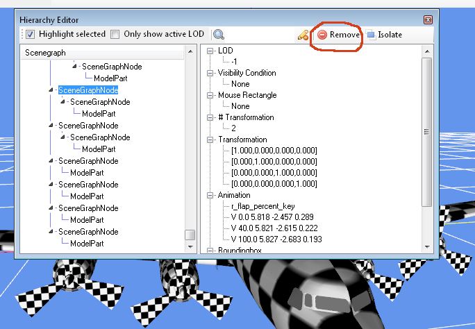
9.
Now scroll down to near the bottom of the file and while
holding
down the Shift key, click the bottom ModelPart or SceneGraphNode
attached to the same vertical line as the SceneGraphNode you click on
in the image above.
All nodes between the prop part and the bottom of the file should
be highlighted (if there is a Crash Tree at the bottom of the file, do
not highlight it).
If the slow props ever turn red STOP!
You have selected something wrong. Once you're sure, press the Remove button.
Repeat this for each vertical line of parts below your slow prop
parts. There is often a list of ModelParts at the bottom of the
file, remove those too. Do NOT remove the Crash Tree if present.
Your bottom prop node should now be at the bottom of the listing, except for the crash tree (if present):
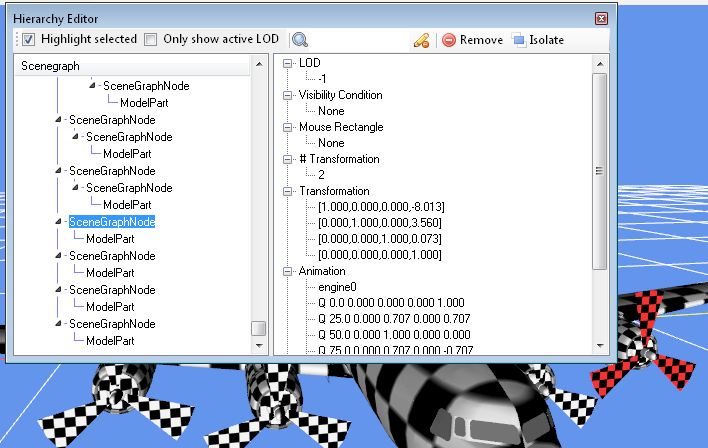
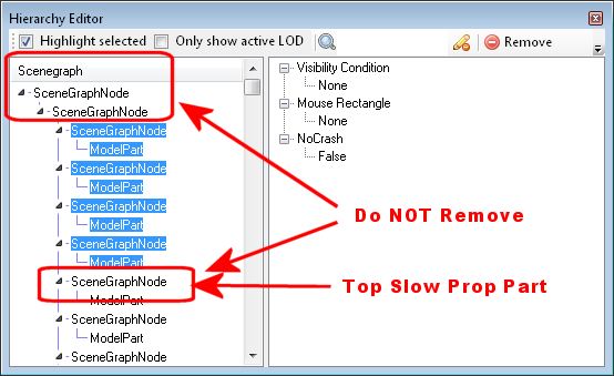
10. Click on the SceneGraphNode above our bottom prop part, because we need to delete nodes until we find the next slow
prop node above that. Luckily they are often listed together, so click on
the SceneGraphNode directly above the bottom prop part, and see if
this is a slow prop part. In the case of the DC-6B all 4 are together, so
that's easy and we can move on. If they are not all together, remove any SceneGraphNodes between
the slow prop parts. Do this one by one - click on the SceneGraphNode of a given node. If it is not a slow prop part (i.e. it doesn't turn red), then press the
Remove button. If it is a slow prop part, skip it and keep moving
upward until you have all of the slow prop parts together.
Here is a part that is not a slow prop part - press the Remove button:
Here is a slow prop part - skip it and continue moving up:
Here
is a demonstration of how it should look when you have all 4 slow prop
parts at the bottom of the file - The selection is just for the
demonstration, you do not need to do this. Other models may
appears slightly different, but should have the same basic structure.
11.
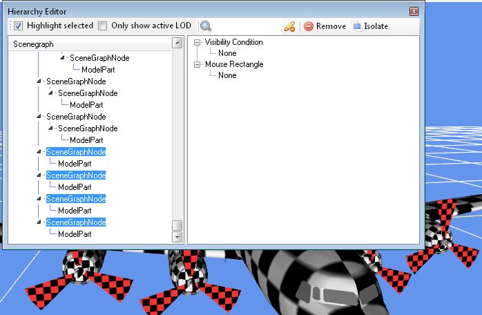
Now that we have all our props at the bottom of the file, we can select all the nodes to almost the top of the listing.
If the slow props ever turn red STOP!
You have selected something wrong. Click the SceneGraphNode above your top prop part:
Use the scroll bar to move up the listing, keeping track of the vertical line that your prop parts are on.. Holding down the Shift key,
click the ModelPart or SceneGraphNode indicated below (it's the top
ModelPart or SceneGraphNode of the vertical line your prop parts are
attached to). Check that the prop parts are NOT RED. Press the Remove button: If you are near the top of the file, see the next step.
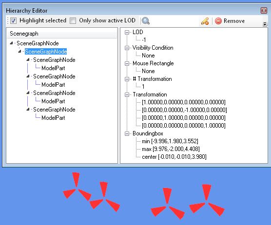
12. Now scroll up to the top of the file and select any parts above your prop parts, but DO NOT include any ModelParts or SceneGraphNodes that start a new vertical line to the right of the one it is on:
13. When you are done it should look like something like this (the number of prop parts will vary with the aircraft):
14. Close the Hierarchy Editor with the red X (all such editors are closed with the red X).
ASSIGNING THE PROP PART ANIMATION AND VISIBILITY DEFINITIONS
15.
Now we get to assign proper animations and visibility conditions
for each of the slow props. The animations can be assigned from
either the Animation Editor or the Hierarchy Editor, the visibility
conditions only from the Hierarchy Editor.. Since it's easier to
do the animations in the Animation Editor we'll start there.
Close the Hierarchy Editor and open the Animation Editor.
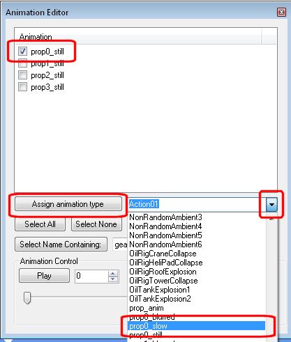
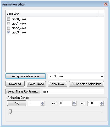
16. Type in prop0 into the box to the right of the
Select Name Containing button and press that button. Now all
the entries for the prop0_still animation should be checked, and the rest
unchecked. In my
DC-6B example, there should be 1. Or just uncheck the other props so only prop0 is checked.
17.
Choose prop0_slow from the drop
down box, and click the Assign Animation Type button.
The prop0_still
line should change to prop0_slow. Repeat steps 6 and 7 for any
other
engine variables in the list - prop1_stil to prop1_slow, prop2_still to
prop2_slow, and prop3_still to prop3_slow. With the DC-6B it should
look like the following when finished. Close the Animation Editor.
18.
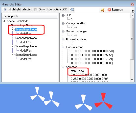
Open the Hierarchy Editor. The slow prop parts should be displayed - click
on one and make sure the slow prop turns red. Click on the
SceneGraphNode and check the animation name.
19.
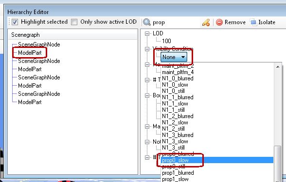
Click on the first ModelPart
below the SceneGraphNode. The slow prop should turn red. Click the word None under the words
Visibility Condition and choose the same visibility condition from
the drop down box as the animation in the SceneGraphNode above it..
For example,
if a SceneGraphNode has an animation name of prop0_slow, then all
ModelParts under that SceneGraphNode (and still within that node)
should receive a visibility condition of prop0_slow. Typically
for slow and
blurred props there will be only one ModelPart for each engine, but
there could be more on complex aircraft.
20.
Repeat this for all prop nodes in this listing, which should be
the number of props on your plane. All
such ModelParts should end up with a visibility condition. Only
ModelParts get visibility conditions, not SceneGraphNodes. Close
the
Hierarchy Editor.
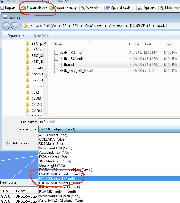
21. Choose Export Object (menu) and change the drop down box to FSX MDL Object
(or another MDL format if exporting to another sim). Give it a name that makes sense to you. I will use
dc6b_props_slow.mdl for the DC-6B example. Save into the
same folder as your aircraft MDL file. A red error line may appear in the log saying that this is not a
supported MDL type. This has never caused a problem for me.
Don't worry about the other MDL files in the image below.
22.
If you do not get a new MDL created or an error message, then it is likely your
compile process is not working correctly. This will need to be
fixed before you can continue (see the LIMITATIONS section in Part 1).
ISOLATING AND ASSIGNING ANIMATIONS AND VISIBILITIES TO THE BLURRED PROPS AND SAVING THEM
23.
Now we get to do this all over again for the prop_blurred parts.
Import your aircraft MDL file again (in our tutorial it's dc6b.mdl)
into MCX. When the Set Condition Variables box pops up, set the prop0/1/2/3_still variables to 10000. When the plane loads, you
should see the blurred props displayed.
24. Isolate the blurred props as we did the slow props in Steps 5 through 14.
25.
Set the animations and visibilities. Follow Steps 15 through 20 except for the blurred props this time.
In the Animation Editor prop0_still is assigned to prop0_blurred,
prop1_still to prop1_blurred, prop2_still to prop2_blurred, and
prop3_still to
prop3_blurred. In the Hierarchy Editor the visibilities are also
assigned prop0/1/2/3_blurred, but to the ModelParts.
26. When you have the blurred props isolated choose Export Object, check the drop down box is FSX MDL Object
(or your sim's format), and save as something like
dc6b_props_blurred.mdl.
Next: PART THREE -FS2004 IMPORT